
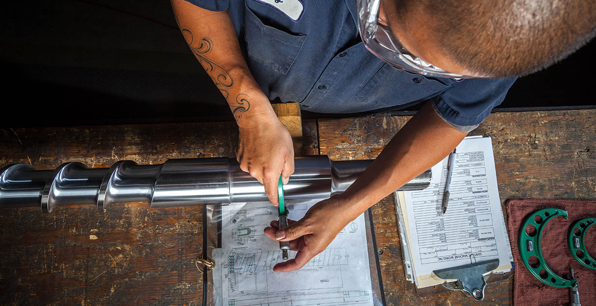
Quick Reference for Injection & Extruder Screw Replacement
This quick reference guide outlines recommended screw and barrel clearance and wear tolerances for injection molding and extrusion applications.
Understanding the proper clearance between screw and barrel helps maintain performance, reduce wear, and prevent processing issues. Use the chart below to evaluate barrel wear measurement and determine when replacement is needed.
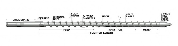
Injection Molding & Extruder Screw Barrel Wear Chart
| Screw Size | New Screw Clearance | Worn Screw Clearance | Max Wear Clearance |
| ½” | 0.003 – 0.004” | 0.008 – 009” | 0.012 – 0.015” |
| 1” | 0.003 – 0.004” | 0.018” | 0.020” |
| 1 – 1/2” | 0.005 – 0.008” | 0.020” | 0.025” |
| 2 – 1/2” | 0.007 – 0.010” | 0.021” | 0.030” |
| 3 – 1/2” | 0.010 – 0.012” | 0.030” | 0.036” |
| 4 – 1/2” | 0.010 – 0.013” | 0.030” | 0.039” |
| 6” | 0.013 – 0.016” | 0.039” | 0.048” |
| 8” | 0.016 – 0.019” | 0.048” | 0.057” |
| 10” | 0.020 – 0.025” | 0.060” | 0.075” |
| 25mm | 0.003 – 0.005 | 0.013 – 0.014 | 0.019 – 0.020 |
| 30mm | 0.003 – 0.005 | 0.014 – 0.015 | 0.021 – 0.022 |
| 40mm | 0.004 – 0.005 | 0.014 – 0.015 | 0.022 – 0.023 |
| 60mm | 0.005 – 0.006 | 0.016 – 0.017 | 0.028 – 0.029 |
| 80mm | 0.006 – 0.007 | 0.019 – 0.020 | 0.034 – 0.035 |
| 90mm | 0.009 – 0.010 | 0.021 – 0.022 | 0.036 – 0.037 |
| 100mm | 0.009 – 0.010 | 0.024 – 0.025 | 0.041 – 0.042 |
| 120mm | 0.012 – 0.013 | 0.030 – 0.031 | 0.049 – 0.050 |
| 140mm | 0.014 – 0.015 | 0.034 – 0.035 | 0.055 – 0.056 |
Have a question or want to get started on your next project?
Santa Fe Machine Works, Inc.
A Family Tradition of Excellence Since 1923

